|
|
| O + H2
--> O + H2 |
- Elastic/direct
scattering |
|
|
| H+ + O2
--> H + O2+ |
- Charge transfer |
|
|
| O + H2
--> O+ + H2 + e- |
- Electron
loss (or stripping) |
|
|
| O + H2
--> O- + H2+ |
- Electron capture |
|
|
For a particular process, the cross section and the differential cross section (DCS) are
measured at 3-5 projectile energies in the 0.5-5 keV range. The
charge transfer apparatus is described below. The same basic
apparatus is used to measure direct scattering cross sections,
although the analysis differs somewhat.
The electron-capture and -loss
apparatus, is significantly different from that used for
charge transfer and direct scattering and is described separately
.
| |
Charge Transfer Apparatus
|
The schematic below represents the charge transfer scattering
apparatus. For stable targets, such as N2, a simple
target cell is adequate.
Schematic of the charge transfer apparatus
- Ions are extracted from a low-pressure plasma-type ion source,
accelerated to the desired energy (0.5- 5keV) and focused by
an electrostatic lens.
- The ion beam is then mass-selected by a pair of 60 degree
sector magnets and passes through a pair of collimating apertures
before traversing the target cell.
- A position-sensitive detector (PSD) on the beam axis 26 cm
beyond the target cell is used to monitor both the primary ion
beam and the fast neutral atoms resulting from charge transfer
collisions.
- The pressure in the target cell (typically 10 mtorr) is chosen
to ensure that single collision conditions obtain.
- The relatively short target cell length, approximately 1
mm, ensures that the collisions occur within a very well defined
region and as the PSD records the position of each incident neutral
particle the scattering angle is easily obtained.
- The number density of the target gas is obtained from a measurement
of the target gas pressure using a capacitance diaphragm gauge.
- Knowledge of the target cell length, the target number density,
the primary beam flux, and the flux and position of the scattered
neutrals allows us to determine the absolute differential and
integral charge transfer cross sections.
- A brief outline of the data analysis is given with the typical charge
transfer results. For further details see Lindsay et al., Phys. Rev. A 53, 212
(1996).
| |
Atomic Oxyen Target Apparatus
|
In order to conduct scattering experiments with atomic oxygen
it is necessary to have some sort of well defined atomic oxygen
target. However, it is very difficult to produce a well characterized
atomic oxygen target because oxygen atoms recombine very quickly
to form molecules. We have overcome this problem by having a
constant flow of partially dissociated oxygen gas pass through
a target cell. The oxygen gas is initially dissociated by a microwave
discharge and then flows through Teflon conduit (which inhibits
recombination) to the target region. The atomic oxygen pressure
in the target cell is determined using a calibrated mass spectrometer
which was specially designed for the purpose.
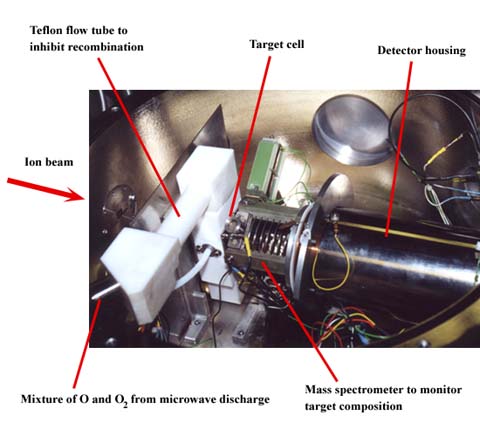
The picture below shows the interior of the atomic oxygen
target apparatus. Only the target region, mass spectrometer,
and detector housing are shown. The ion source and the magnets
(just to the left of the picture) are not shown. During scattering
measurements the ion beam enters the chamber from the left passes
through the target cell and impacts the detector on the right.
The spectrometer acceleration stage (segmented structure) must
be rotated off the ion beam axis during these measurements.When
scattering measurements are not being performed this stage is
manually rotated into the position shown and the mass spectrometer
can then be used to sample the gas effusing from the target cell
exit aperture. For further details see Lindsay et al., Phys. Rev. A 53, 212
(1996).
Atomic oxygen target scattering apparatus
Physics
and Astronomy | Rice Quantum
Institute| Rice Space Institute
Rice University
Updated May 3, 2005
|